Chưa có sản phẩm trong giỏ hàng.


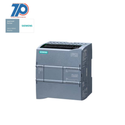
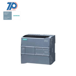
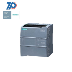
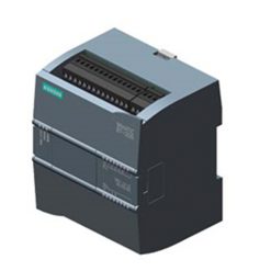
6ES7352-5AH01-0AE0 – SIMANIC S7-300
--- Giá chưa bao gồm VAT ----
Giá có thể thay đổi, vui lòng liên hệ trước khi đặt hàng (Luôn có giá tốt khi mua số lượng nhiều)
Bảo hành 12 tháng khi mua tại TPNewtech.
Thời gian vận chuyển:
Thời gian giao hàng ước tính từ 1 - 5 ngày trên toàn quốc.
Luôn có chương trình hỗ trợ dự án công trình
-> Hãy Liên hệ ngay cho chúng tôi

Chi Tiết Sản Phẩm
Material ID: 6ES7352-5AH01-0AE0
- SIMATIC S7-300, FM352-5 with NPN output
- High Speed Boolean Processor, for high-speed linking
- 12 DI
- 8 DO
- 1 encoder interface for RS422 incr./SSI encoder
- SIMATIC ET 200M is a modular and universally applicable I/O system for the control cabinet in IP20
- Can be used as a central I/O on an S7-300
- In a distributed configuration on a PROFINET or PROFIBUS ET 200M interface module
- Up to 12 IO modules can be inserted into each station
- Standardized setup of all modules simplifies logistics and stocking of spare parts
- Can be used for both standard and safety-oriented applications
- Up to 12 multi-channel signal modules and function modules can be used as I/O modules
- Supports modules with extended user data, such as HART modules with HART auxiliary variables
- Offers FastConnect fast connection technology for easy wiring without stripping
Additional Information
Support
| Technical Data | Manuals / Links |
Thông số kỹ thuật: PLC S7-300 6ES7352-5AH01-0AE0
- Nhãn hiệu/Nhà sản xuất: Siemens
- Mã sản phẩm: 6ES7352-5AH01-0AE0
- Loại sản phẩm: CPU Module
- Điện áp nguồn: 24 V dc
- Program capacity: 128 kB
- Current consumption: 135 mA @ 5 V dc
- Để sử dụng với: SIMATIC PG
- Number of digital inputs: 8
- Number of digital outputs: 8
SIMATIC S7-300, FM352-5 WITH SINK OUT, HIGH SPEED BOOLEAN PROCESSOR, FOR HIGH-SPEED LOGIC OPERATION 12 DI, 8 DO, 1 ENCODER INTERF. FOR RS422 INCR./SSI ENCODER
Toàn Phát đối tác phân phối độc quyền các thiết bị công nghiệp SIEMENS – 6ES7352-5AH01-0AE0 chính hãng đầy đủ hóa đơn chứng từ và nguồn gốc xuất sứ.
Tất cả sản phẩm của Toàn Phát được bảo hành 12 tháng.
Chính sách khi mua hàng SIMATIC S7-300
Chính sách bảo hành
Khi mua hàng tại TPNEWTECH, tất cả sản phẩm của chúng tôi được bảo hành 12 tháng. Luôn sẵn sàng hỗ trợ sửa chữa và bảo trì lắp đặt cho tất cả KH dù KH có mua nhiều hay mua ít.
Hỗ trợ sửa chữa tận nơi đối với KH ở khu vực nội thành TP.Hồ Chí Minh.
KH ở xa có thể gửi hàng thông qua các bên vận chuyển để được sửa chữa.
Chính sách vận chuyển
Tất cả KH khi mua hàng có địa chỉ nhận hàng ở khu vực TP.Hồ Chí Minh sẽ được miễn phí hoàn toàn chi phí giao hàng (thời gian giao hàng nội thành HCM từ 1-3 ngày làm việc).
Đối với các KH ngoại thành tùy vào số lượng đặt hàng lớn hay nhỏ chúng tôi sẽ linh động tối ưu chi phí giao hàng cho quý khách.
Hướng dẫn mua sản phẩm SIEMENS – 6ES7352-5AH01-0AE0
Để mua hàng quý khách có thể liên hệ với chúng tôi bằng cách gọi điện thoại hoặc Zalo

Hoặc gọi qua số điện thoại Hotline: (+84) 903 908 082
Thông tin kỹ thuật bổ sung 6ES7352-5AH01-0AE0
 | SIMATIC S7-300, FM352-5 with NPN output, High Speed Boolean Processor, for high-speed linking, 12 DI, 8 DO, 1 encoder interface for RS422 incr./SSI encoder | |
| Supply voltage | ||
| Load voltage L+ | ||
| ● Rated value (DC) | 24 V | |
| ● permissible range, lower limit (DC) | 20.4 V | |
| ● permissible range, upper limit (DC) | 28.8 V | |
| ● Reverse polarity protection | Yes | |
| Input current | ||
| from load voltage1L+, max. | 150 mA; typ. 60 mA | |
| from load voltage 2L+ (without load), max. | 200 mA; typ. 60 mA, DI/DO supply | |
| from load voltage 3L+ (with encoder), max. | 600 mA; typ. 80 mA plus encoder supply | |
| from load voltage 3L+ (without load), max. | 200 mA; typ. 80 mA | |
| from backplane bus 5 V DC, typ. | 135 mA | |
| Encoder supply | ||
| 5 V encoder supply | ||
| ● 5 V | Yes | |
| ● Short-circuit protection | Yes; Electronic overload protection; no protection on applying a normal or counter voltage. | |
| ● Output current, max. | 250 mA | |
| 24 V encoder supply | ||
| ● 24 V | Yes | |
| ● Short-circuit protection | Yes; Overvoltage and overheating protection if overloaded; diagnostics if output reaches temperature limit; no protection on applying a normal or counter voltage | |
| ● Output current, max. | 400 mA | |
| Power loss | ||
| Power loss, typ. | 6.5 W | |
| Memory | ||
| Type of memory | RAM | |
| Memory size | 128 kbyte; required for operation, MMC | |
| Digital inputs | ||
| Number of digital inputs | 8; Standard and up to 12 with 24 V DC encoder inputs as digital inputs | |
| Input voltage | ||
| ● Rated value (DC) | 24 V | |
| ● for signal “0” | -30 to +5 V | |
| ● for signal “1” | +11 to +30V | |
| Input current | ||
| ● for signal “0”, max. (permissible quiescent current) | 1.5 mA | |
| ● for signal “1”, typ. | 3.8 mA | |
| Input delay (for rated value of input voltage) | ||
| ● Input frequency (with a time delay of 0.1 ms), max. | 200 kHz | |
| ● programmable digital filter delay | None, 5 µs, 10 µs, 15 µs, 20 µs, 50 µs, 1.6 ms | |
| ● Minimum pulse width for program reactions | 1 µs, 5 µs, 10 µs, 15 µs, 20 µs, 50 µs, 1,6 ms | |
| for standard inputs | ||
| — at “0” to “1”, max. | 3 µs; typ. 1.5 µs | |
| Cable length | ||
| ● shielded, max. | 600 m | |
| ● unshielded, max. | 100 m; Shielded cable recommended if filtering delay is set to less than 1.6 ms | |
| Digital outputs | ||
| Number of digital outputs | 8 | |
| Current-sinking | Yes | |
| Current-sourcing | No | |
| Short-circuit protection | Yes; Overvoltage protection, thermal protection | |
| ● Response threshold, typ. | 1.7 to 3.5 A | |
| Limitation of inductive shutdown voltage to | 2M -45 V typ., (-40 V to -55 V); comment: no protection against inductive kickback >55 mJ | |
| Controlling a digital input | No | |
| Switching capacity of the outputs | ||
| ● on lamp load, max. | 5 W | |
| Output voltage | ||
| ● Rated value (DC) | 24 V | |
| ● for signal “0”, max. | 28.8 V | |
| ● for signal “1”, max. | 0.5 V | |
| Output current | ||
| ● for signal “1” rated value | 0.5 A; At 60 °C | |
| ● for signal “1” permissible range for 0 to 60 °C, min. | 5 mA | |
| ● for signal “1” permissible range for 0 to 60 °C, max. | 600 mA | |
| ● for signal “0” residual current, max. | 1 mA | |
| Output delay with resistive load | ||
| ● “0” to “1”, max. | 1 µs; 0.6 µs 50 mA / 1.0 µs 0.5 A | |
| ● “1” to “0”, max. | 1.5 µs; 1.7 µs 50 mA / 1.5 µs 0.5 A | |
| Parallel switching of two outputs | ||
| ● for uprating | Yes; 2 | |
| Switching frequency | ||
| ● with resistive load, max. | 100 kHz; 20 kHz at 0.5 A; 100 kHz at 0.25 A | |
| ● with inductive load, max. | 2 Hz; 2 Hz at 0.5 A with external commutator diodes; 0.5 Hz at 0.5 A without external commutator diodes | |
| ● on lamp load, max. | 10 Hz | |
| Cable length | ||
| ● shielded, max. | 600 m | |
| ● unshielded, max. | 100 m | |
| Encoder | ||
| Connectable encoders | ||
| ● Incremental encoder (symmetrical) | Yes | |
| ● Incremental encoder (asymmetrical) | Yes | |
| ● Absolute encoder (SSI) | Yes | |
| ● 2-wire sensor | Yes | |
| — permissible quiescent current (2-wire sensor), max. | 1.5 mA | |
| Encoder signals, incremental encoder (symmetrical) | ||
| ● Trace mark signals | A, notA, B, notB | |
| ● Zero mark signal | N, notN | |
| ● Input voltage | 5 V difference signal (phys. RS 422) | |
| ● Input frequency, max. | 500 kHz | |
| ● Cable length, shielded, max. | 100 m; 100 m with 24 V supply and 500 kHz; 32 m with 5 V supply and 500 kHz | |
| Encoder signals, incremental encoder (asymmetrical) | ||
| ● Trace mark signals | A, B | |
| ● Zero mark signal | N | |
| ● Input voltage | 24 V | |
| ● Input frequency, max. | 200 kHz | |
| ● Cable length, shielded, max. | 50 m; Cable length, HTL incremental encoder, Siemens, type 6FX2001-4: 50 kHz, 25 m shielded, max., 25 kHz, 50 m shielded, max. | |
| Encoder signals, absolute encoder (SSI) | ||
| ● Data signal | DATA, notDATA | |
| ● Clock signal | CK, notCK | |
| ● Telegram length, parameterizable | 13 or 25 bit | |
| ● Clock frequency, max. | 1 MHz; 125 kHz, 250 kHz, 500 kHz or 1 MHz | |
| ● Cable length, shielded, max. | 320 m; At 125 kHz | |
| ● Monoflop time | settable: 16/32/48/64 µs | |
| ● Listening mode | Yes; one or two stations | |
| ● Multiturn | Yes; 25 bit message frame | |
| Encoder signal evaluation | ||
| ● Counting direction, forward | Yes | |
| ● Counting direction, backward | Yes | |
| Response times | ||
| Input- to output response time | 5 V input to 24 V output, 0 filter: 1 to 4 µs (typ.); 24 V input to 24 V output, 0 filter: 2 to 6 µs (typ.) | |
| Interfaces | ||
| Point-to-point connection | ||
| ● Updating times | PLC interface: 1.7 ms | |
| Interrupts/diagnostics/status information | ||
| Alarms | ||
| ● Diagnostic alarm | Yes; 1L, 2L, 3L missing; MMC error; output overload (8); encoder supply overload; differential wire break; parameterization errror; SSI message frame overflow | |
| ● Hardware interrupt | Yes; 8 available; for generation by user program | |
| Diagnostic messages | ||
| ● Wire-break in signal transmitter cable | Yes | |
| ● Overflow/underflow | Yes | |
| ● missing load voltage | Yes | |
| Diagnostics indication LED | ||
| ● RUN/STOP LED | Yes | |
| ● Module supply 5 V DC (green) | Yes | |
| ● I/O status IOF (red) | Yes | |
| ● Micro Memory Card error MCF (red) | Yes | |
| ● Group error SF (red) | Yes | |
| ● Status indicator digital input (green) | Yes; I 0 to I 11 | |
| ● Status indicator digital output (green) | Yes; Q 0 to Q 7 | |
| ● Overload encoder supply voltage 24 V F (red) | Yes | |
| ● Overload encoder supply voltage 5 V F (red) | Yes | |
| Counter | ||
| Counting range, description | Counting range (16-bit counters): -32 768 to 32 767 (user-specific within this range); counting range (32-bit counters): -2 147 483 648 to 2 147 483 647 (user-specific within this range) | |
| Counting range, lower limit | -2 147 483 648 | |
| Counting range, upper limit | 2 147 483 647 | |
| Counting mode | ||
| ● Counting mode, individual | Yes | |
| ● Counting mode, continuous | Yes | |
| ● Counting mode, periodic | Yes | |
| Potential separation | ||
| between 1L and 2L and 3L | Yes | |
| Potential separation digital inputs | ||
| ● Potential separation digital inputs | Yes; Yes CPU, I/O and sensor units are isolated | |
| Ambient conditions | ||
| Ambient temperature during operation | ||
| ● min. | 0 °C | |
| ● max. | 60 °C | |
| Ambient temperature during storage/transportation | ||
| ● min. | -40 °C | |
| ● max. | 70 °C | |
| Configuration | ||
| Programming | ||
| ● Program cycle time (scan) | 1 µs | |
| Connection method | ||
| required front connector | 1x 40-pin | |
| Dimensions | ||
| Width | 80 mm | |
| Height | 125 mm | |
| Depth | 120 mm | |
| Weights | ||
| Weight, approx. | 434 g; Module weight: approx. 434 g (with 1L connection and without I/O connection or MMC); shipping weight: approx. 500 g (with bus and 1L connection and without I/O connection or MMC) | |
| last modified: | 05/28/2020 | |
| Trọng lượng | 0.54 kg |
|---|---|
| Country of Origin | DE |
Tất cả thiết bị điện – điện tự động SIEMENS cung cấp đến Khách Hàng như S7-1200, S7-1500, HMI, biến tần,… đều được nhập mẫu mã mới nhất từ Đức về Việt Nam.
Tại TPNewtech, chúng tôi còn hỗ trợ tư vấn và cung cấp giải pháp tốt và tiết kiệm chi phí nhất đến Khách Hàng.
Chương Trình Khuyến Mãi

Sản Phẩm Tương Tự
Giảm giá!
Giá gốc là: 9,155,000₫.3,635,000₫Giá hiện tại là: 3,635,000₫.
Giảm giá!
Giá gốc là: 13,860,000₫.5,800,000₫Giá hiện tại là: 5,800,000₫.


Đánh giá
Chưa có đánh giá nào.